technological innovation
Considerations for Stamping Die Design in Chassis Manufacturing
With the rapid development of the socio-economic landscape, production technology has continuously advanced. In order to better meet the evolving market demands, this article will delve into the design of stamping dies for chassis manufacturing.
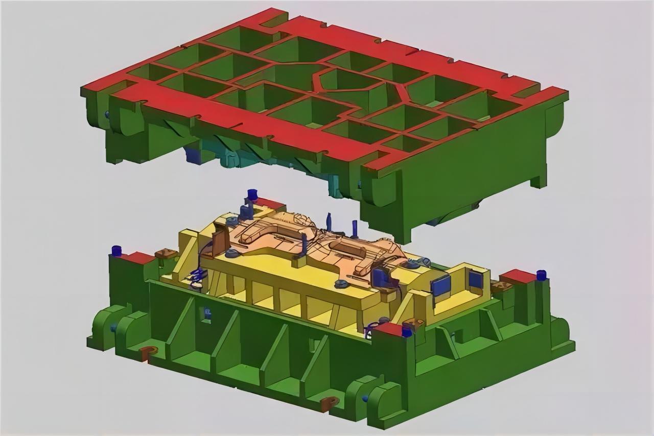
Chassis Longitudinal Beam Stamping Die
The chassis longitudinal beam is an important component of the chassis assembly, and its design quality directly impacts the overall quality of the chassis product. Additionally, the longitudinal beam is the longest part in the chassis assembly, which adds to the complexity of the stamping process and increases the workload. Therefore, stringent requirements are placed on the stamping of the chassis longitudinal beam. Practical production has shown that the use of drilling templates can ensure the accuracy of hole positions. On the other hand, due to the cross-sectional shape of the longitudinal beam being a groove-type double right-angle bending formation, methods such as free bending forming and double right-angle contact bending forming can be employed.
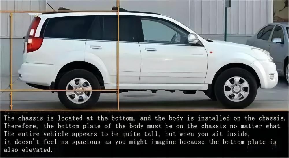
Manufacturing Process Analysis
The design of chassis longitudinal beams is divided into left and right components. Non-variable cross-section longitudinal beams can be directly stamped into shape using a set of molds. However, when the longitudinal beam components have a variable cross-section, a more systematic stamping arrangement is required. The following figure depicts a longitudinal beam with a variable cross-section:
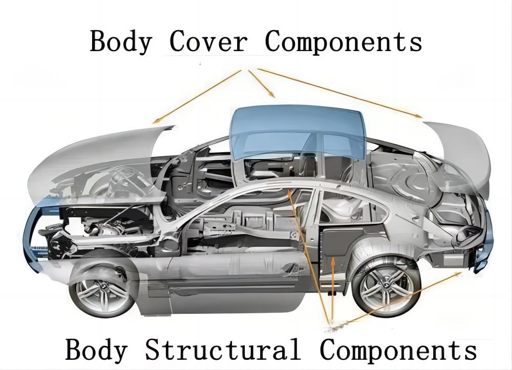
Then, we divide the mold into three parts: front section, middle section, and rear section. The front and middle sections are responsible for stamping the right side of the longitudinal beam, while the rear and middle sections are responsible for stamping the left side of the longitudinal beam. This working approach is chosen to effectively reduce the cost of mold manufacturing and enhance the efficiency of stamping. After implementing this design, we have obtained the stamping result diagram as shown below, where A+B represents the right side of the stamped longitudinal beam, and B+C represents the left side of the stamped longitudinal beam:
If the stamping equipment area becomes a factor during operation, different inserts can be added to the left and right sides of the variable cross-sections. This is done to ensure consistent stamping results on both sides.
Analysis of Some Stamped Components
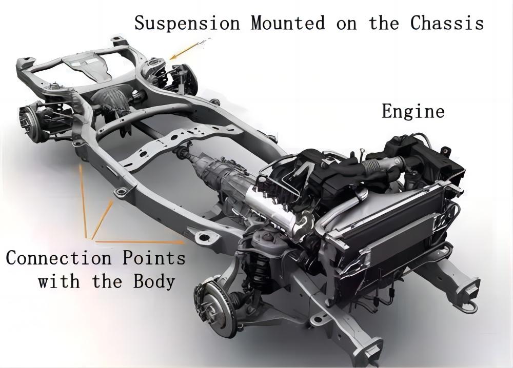
①Manufacture of Crossbeam Stamping Die
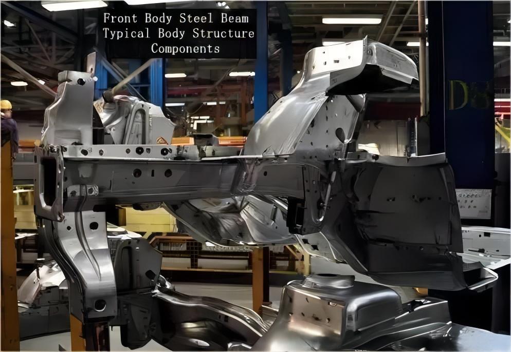
In the design of the crossbeam stamping die, you can refer to the following two diagrams for design. In general, agricultural transport frames have 6 crossbeams, and for frames without variable cross-sections, each crossbeam has the same width. Therefore, a set of dies can be designed for stamping. However, for frames with variable cross-sections in the longitudinal beams, the widths of each crossbeam are quite different, and the versatility of the die will also be greatly limited. Different sets of inserts can be manufactured to complete the entire stamping process. The frame requires the middle section of the crossbeam to be the variable cross-section crossbeam. For this purpose, the design of the die can be divided into three major parts: front, middle, and rear sections. The middle section can be made according to the different variable cross-sections, while the design of the front and rear sections can ensure its stability and better adapt to the bending forming requirements of each type of crossbeam in the end.
②Design of Remaining Parts Stamping Dies
The diagram below represents a workpiece formed by U-shaped double right-angle bending, made using Q235 steel plate through stamping. The stamping equipment used ranges from 30 tons to 100 tons, and the die used is formed by welding a 30mm thick Q235 steel plate.
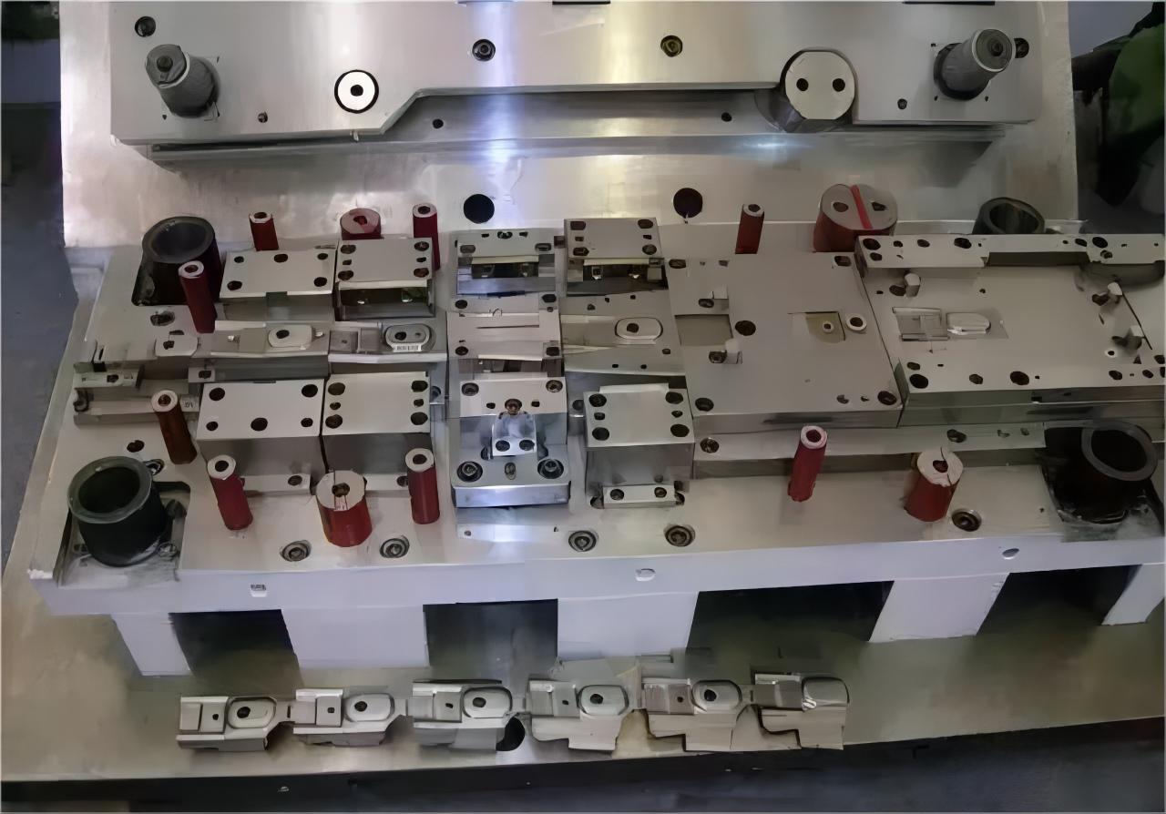
For precision parts, after cutting the steel plate, it wasn't further processed; it was simply smoothed using a handheld grinder after welding. Simple dies like these lack a dedicated discharge mechanism, which can significantly affect practical work. Based on practical production experience and requirements, we analyze two methods for discharging. The first method involves setting the workpiece in the concave die and using a scraping plate for discharge. The second method involves setting the workpiece in the convex die and using a pulling mechanism for discharge.
The scraping plate discharge involves reinforcing a scraping plate at the position of the concave die base. This plate cannot move up and down but can move left and right. When the scraping plate is pulled away, it forms the stamping shape. When forming on the convex die, the scraping plate A should be moved to the upper part of the convex die in time, encompassing the entire workpiece. This allows for the disengagement.
The pulling discharge method involves placing a bottom plate at the position of the concave die base. After forming, fix the bottom plate on the line B that is attached to the upper part of the convex die. As the convex die moves upward, it pulls the bottom plate, resulting in the extraction of the workpiece trapped in the concave die.
Summary
Through the detailed analysis of the materials above, we have gained a general understanding of the design principles and unique design processes of chassis longitudinal beam stamping dies. We have addressed the specialized issues related to the use of stamping equipment in manufacturing chassis longitudinal beam stamping dies. The article also provides a brief overview of knowledge related to the manufacturing of crossbeam stamping dies.
Throughout the entire text, we've essentially discussed the issue of outdated manufacturing equipment, focusing on resolving and analyzing the contradictions between advanced production capabilities and outdated production machinery.
RELATED NEWS
- Not sure about the T4, T5, and T6 materials of aluminum profiles? This article h 2024-03-20
- How to use aluminum profile section design skills to solve extrusion production 2024-03-19
- Factors affecting the life of trimming and punching molds 2024-03-12
- Overview of Steel/Aluminum Welding Technology 2024-02-29
- Steel belt conveying direction 2023-09-26
CATEGORIES
LATEST NEWS
CONTACT US
Contact: Manager:Miss Jasmien
Phone: +8618825429836
E-mail: info@gdaa-cn.com
Whatsapp:+8618825429836
Add: Headquarter:No.8,Yixian Road,GDAA Mansion,Guangfo Zhicheng, Dali Town,Foshan,Guangdong.China
